MEASUREMENT IN FITTING EYEGLASSES - PART II
Previously, we discussed the IPD measurement for distance and near vision. In this blog post, we will discuss how to measure the Vertex Distance and the Base Curve of the Lens.
VERTEX DISTANCE:
The distance between the back of an eyeglass lens and the front of the eyeglass wearer's eye is the vertex distance (Fig1.1). A vertex distance of 13.5 mm is considered average, but vertex distance can range from 5 mm to more than 26 mm. The most effective fit for eyeglasses usually is obtained by fitting the frame as close to the eye as possible without the eyelashes touching the lens.

Positioning a patient's eyeglasses at a vertex distance other than that used during refractometry will change the effective power of the lenses. The amount of change depends on the power of the lens. For low-powered lenses, the patient will not notice a difference in vision correction. But for high-powered lenses, a small alteration in vertex distance will make a considerable and noticeable change in the effective power of both the spherical and the cylindrical components of the lens. For example, if a patient's refractive prescription is less than or equal to minus or plus 5 dioptres, an accurate assessment of vertex distance is not required to ensure proper eyeglass prescription. But if the prescription calls for more than minus or plus 5 dioptres, the vertex distance should be measured during refractometry to avoid refractive errors that could lead to vision difficulties with the eyeglasses. When recording the ophthalmologist's refractive prescription for a patient, the ophthalmic medical assistant should always include a vertex distance on lens powers greater than plus or minus 5 diopters. A specially designed instrument called a distometer is used to measure vertex distance accurately. Instructions for measuring vertex distance appear in the table "Using a Distometer."
USING A DISTOMETER:
1. Ask the patient to close both eyes.
2. Gently rest the fixed arm of the distometer caliper on the closed eyelid and carefully place the movable caliper arm against the back surface of the trial lens or eyeglass lens (see the figure)
3. Record the separation distance between these two surfaces from the millimeter scale on the distometer. (Note: This scale allows for an average eyelid thickness).

BASE CURVE:
The base curve of a lens is the original single curve on the front or back surface of a lens "blank" supplied by a manufacturer. Using the single curve as a basis for measurement, the laboratory technician grinds additional curves on the lens surfaces to achieve the final power and refractive correction of the lens. The power of a lens equals the algebraic difference difference between the power of the front curve and that of the back curve, and many different combinations of base curves and other curves can be used to arrive at the same power. Although base curve can exist on either the front or back surface of a lens, most single-vision lenses have a base curve on the front surface.
Patients become accustomed to wearing lenses ground with a particular base curve. Changing the base curve when a new pair of lenses is prescribed can cause the patient discomfort, ranging from a perception of visual distortion to dizziness and nausea. Thus, when ordering replacement lenses or supplying the patient with a second pair of glasses, the optician must duplicate the base curves for both pairs of eyeglasses to ensure that the patient can comfortably wear the second pair. The ophthalmic medical assistant may be required to measure the base curves of lenses to assure that new lenses have been ground correctly or to help determine the source of a patient's visual complaints.
The Geneva lens clock is the instrument used to measure the base curve of a eyeglass lens. The lens clock is caliberated in diopters and has three blunt pins at its foot, the outer two fixed and the central one movable (Fig 1.3). When the pins are held against a flat surface, the indicator hand of the lens clock points to zero. When the instrument is placed against a concave lens surface, the indicator will point to minus(-), or red, numbers; placed against a convex lens surface, the indicator will point to the plus(+), or black, number scale. When measuring the multifocal lens, always keep the pins of the lens clock away from the multifocal segment; if the pins impinge on the multifocal segment, an error in base curve measurement could result (Fig 1.4). The procedure for measuring base curve is outlined in the box "Using a Geneva Lens Clock".


USING A GENEVA LENS CLOCK:
1. Place the front surface of a single-vision lens against the pins in the 180* meridian (see the figure).

2. Note the position of the pointer on the clock dial and record this number. Remember: The red scale indicates a concave (minus) surface; the black, a convex (plus) surface.
3. Rotate either the lens clock or the lens to the 90* meridian.
a. If the reading remains constant, the reading noted in step 2 is the base curve.
b. If the reading changes on rotation, the lens surface has a cylindrical component. The difference between the lower and the higher readings represents the amount of cylinder present. The weaker, or lesser, number of the two measured on the front surface is the base curve.
Note: The orientation of the three contact points on the lens clock at the maximum and minimum readings corresponds to the meridians of lens power.

Previously, we discussed the IPD measurement for distance and near vision. In this blog post, we will discuss how to measure the Vertex Distance and the Base Curve of the Lens.
VERTEX DISTANCE:
The distance between the back of an eyeglass lens and the front of the eyeglass wearer's eye is the vertex distance (Fig1.1). A vertex distance of 13.5 mm is considered average, but vertex distance can range from 5 mm to more than 26 mm. The most effective fit for eyeglasses usually is obtained by fitting the frame as close to the eye as possible without the eyelashes touching the lens.

Fig 1.1 Vertex Distance
Positioning a patient's eyeglasses at a vertex distance other than that used during refractometry will change the effective power of the lenses. The amount of change depends on the power of the lens. For low-powered lenses, the patient will not notice a difference in vision correction. But for high-powered lenses, a small alteration in vertex distance will make a considerable and noticeable change in the effective power of both the spherical and the cylindrical components of the lens. For example, if a patient's refractive prescription is less than or equal to minus or plus 5 dioptres, an accurate assessment of vertex distance is not required to ensure proper eyeglass prescription. But if the prescription calls for more than minus or plus 5 dioptres, the vertex distance should be measured during refractometry to avoid refractive errors that could lead to vision difficulties with the eyeglasses. When recording the ophthalmologist's refractive prescription for a patient, the ophthalmic medical assistant should always include a vertex distance on lens powers greater than plus or minus 5 diopters. A specially designed instrument called a distometer is used to measure vertex distance accurately. Instructions for measuring vertex distance appear in the table "Using a Distometer."
USING A DISTOMETER:
1. Ask the patient to close both eyes.
2. Gently rest the fixed arm of the distometer caliper on the closed eyelid and carefully place the movable caliper arm against the back surface of the trial lens or eyeglass lens (see the figure)
3. Record the separation distance between these two surfaces from the millimeter scale on the distometer. (Note: This scale allows for an average eyelid thickness).

Fig 1.2 Distometer
BASE CURVE:
The base curve of a lens is the original single curve on the front or back surface of a lens "blank" supplied by a manufacturer. Using the single curve as a basis for measurement, the laboratory technician grinds additional curves on the lens surfaces to achieve the final power and refractive correction of the lens. The power of a lens equals the algebraic difference difference between the power of the front curve and that of the back curve, and many different combinations of base curves and other curves can be used to arrive at the same power. Although base curve can exist on either the front or back surface of a lens, most single-vision lenses have a base curve on the front surface.
Patients become accustomed to wearing lenses ground with a particular base curve. Changing the base curve when a new pair of lenses is prescribed can cause the patient discomfort, ranging from a perception of visual distortion to dizziness and nausea. Thus, when ordering replacement lenses or supplying the patient with a second pair of glasses, the optician must duplicate the base curves for both pairs of eyeglasses to ensure that the patient can comfortably wear the second pair. The ophthalmic medical assistant may be required to measure the base curves of lenses to assure that new lenses have been ground correctly or to help determine the source of a patient's visual complaints.
The Geneva lens clock is the instrument used to measure the base curve of a eyeglass lens. The lens clock is caliberated in diopters and has three blunt pins at its foot, the outer two fixed and the central one movable (Fig 1.3). When the pins are held against a flat surface, the indicator hand of the lens clock points to zero. When the instrument is placed against a concave lens surface, the indicator will point to minus(-), or red, numbers; placed against a convex lens surface, the indicator will point to the plus(+), or black, number scale. When measuring the multifocal lens, always keep the pins of the lens clock away from the multifocal segment; if the pins impinge on the multifocal segment, an error in base curve measurement could result (Fig 1.4). The procedure for measuring base curve is outlined in the box "Using a Geneva Lens Clock".
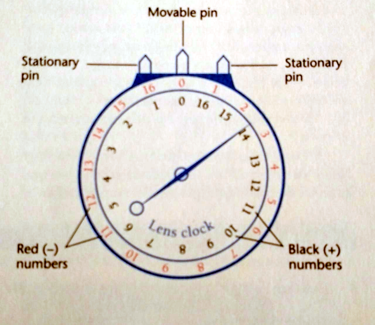
Fig 1.3 The Geneva lens clock for measuring the base curve of a lens

Fig 1.4 Placement of the Geneva lens clock onto a multifocal lens A)Incorrect Placement
B) Correct Placement
USING A GENEVA LENS CLOCK:
1. Place the front surface of a single-vision lens against the pins in the 180* meridian (see the figure).

2. Note the position of the pointer on the clock dial and record this number. Remember: The red scale indicates a concave (minus) surface; the black, a convex (plus) surface.
3. Rotate either the lens clock or the lens to the 90* meridian.
a. If the reading remains constant, the reading noted in step 2 is the base curve.
b. If the reading changes on rotation, the lens surface has a cylindrical component. The difference between the lower and the higher readings represents the amount of cylinder present. The weaker, or lesser, number of the two measured on the front surface is the base curve.
Note: The orientation of the three contact points on the lens clock at the maximum and minimum readings corresponds to the meridians of lens power.
Comments
Post a Comment