LENSOMETRY OR FOCIMETER OR VERTOMETER:
Lensometry is a procedure used to measure the prescription of a patient's existing eyeglass lenses or the power of contact lenses. This technique is often called neutralization, but should not be confused with neutralization as the word applies to retinoscopy. Lensometry is performed (usually by the ophthalmic medical assistant) with a specialized instrument knows as a lensometer.
Lensometry measures four principal properties of Lenses:
1. Spherical and Cylindrical power in dioptres.
2. Axes, if the lenses have a cylinder component.
3. Presence and direction of a prism incorporated into the lenses.
4. Optical centers.
Lensometry performed on a patient's eyeglasses before refraction can provide a starting point for the current refraction. This information is also useful in revealing changes in refractive error. Lensometry also serves to confirm that a patient's new glasses have been made in accordance with the doctor's prescription.
TYPES OF LENSMETERS:
Instruments used to perform lensometry may be either manual or automated. Manual lensometers are known by several brand names. Fig 1.1 shows a manual lensmeter with the significant parts labeled; 1.2 shows a lensmeter in use. To use manual instruments well, the operator needs a thorough understanding of not only lensometry itself, but also the principles of ophthalmic corrective lenses.
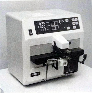
Automated Lensmeters (Fig 1.3) measure an eyeglass lens prescription "at the push of a button." Little understanding of lensometry principles is necessary to operate the instrument. Automated Lensometry can be faster than manual methods, but speed depends on the operator. In addition, these instruments are more expensive than manual ones. Because not all ophthalmology offices have automated equipment, ophthalmic medical assistants should develop basic skills in manual lensometry.


ELEMENTS OF LENSOMETRY:
The first three steps in performing lensometry on lenses of all types are
1. Focusing the instrument eyepiece.
2. Positioning the eyeglass lens to be measured on the spectacle table (or frame-support platform) of the lensmeter.
3. Measuring the sphere power and, if present, cylinder power and axis, either in plus-cylinder or in minus-cylinder form.
Lensometry always begins with focusing the eye-piece, followed by positioning the lenses. For multifocal lenses, the distance portion is positioned and measured first. Sphere and cylinder power may be measured and expressed in either plus- or minus- cylinder form, but because preference for either method may vary from office to office, ophthalmic medical assistants should be able to obtain these measurements in lensometry in both formats. These steps for performing lensometry on single-vision lenses and the distance portion of multifocal lenses are detailed in the box "Performing Basic Lensometry"
PERFORMING BASIC LENSOMETRY:
FOCUSING THE EYEPIECE:
The focus of the lensmeter eyepiece must be verified each time the instrument is used, to avoid erroneous readings.
1. With no lens or a plano lens in place in the lensmeter, look through the eyepiece of the instrument. Turn the power drum until the mires ( the perpendicular crossed lines), viewing through the eyepiece, are grossly out of focus.
2. Turn the eyepiece in the plus direction, normally counterclockwise. This will fog(blur) the target seen through the eyepiece.
3. Slowly turn the eyepiece in the opposite direction until the target is clear, then stop turning. This procedure focuses the eyepiece.
4. Turn the power drum to focus the mires. The mires should focus at a power-drum reading of zero, which is plano. If the mires do not focus at plano, repeat the procedure from step 1.
POSITIONING THE EYEGLASSES:
1. Place the eyeglasses on the movable spectacle table with the earpieces facing away from you. You are now prepared to read the back surface of the lenses, normally the appropriate surface from which to measure.
2. While looking through the lensmeter eyepiece, align the eyeglass lens so that the mires cross in the center of the target. It is usually appropriate to measure the right lens first, followed by the left lens.
MEASURING SPHERE AND CYLINDER POWER:
PLUS-CYLINDER TECHNIQUE:
1. Turn the power drum to read high minus (about -10.00).
2. Bring the closely spaced mires, often called single lines, into sharp focus by rotating the power drum counterclockwise while at the same time rotating the cylinder axis wheel to straighten the single lines where they cross the widely spaced perpendicular set of mires, often called Triple lines.
3. If the single lines and triple lines come into focus at the same time, the lens is a sphere(Figure A). If only the single line focus, you have identified the sphere portion of a sphero-cylinder. In either case, record the power-drum reading at this point as the power of the sphere.

4. If the cylinder power is present, after noting the power-drum reading for the sphere, measure cylinder power by moving the power drum farther counterclockwise (less minus or more plus), bringing the triple lines into sharp focus.(Figure B).

5. Calculate the difference between the first power-drum reading for the focused single lines and the second power-drum reading for the focused triple lines and record this figure as the plus-cylinder power of the lens.
6. Read the axis of the cylinder off the cylinder axis wheel.
MINUS-CYLINDER TECHNIQUE:
1. Turn the power drum to read high plus (about +10.00).
2. Bring the single lines into sharp focus by rotating the power drum clockwise while simultaneously rotating the cylinder axis wheel to straighten the single lines where they cross the perpendicular set of triple lines.
3. If the single lines and the triple lines come into focus at the same time, the lens is a sphere. Record the power-drum reading at this point as the sphere power.
4. If cylinder power is present, move the power drum farther clockwise (more minus or less plus), bringing the triple lines into sharp focus.
5. Calculate the difference between the single-line reading on the power drum and the triple-line reading on the power drum, and record this figure as the minus-cylinder power.
6. Read the axis of the cylinder off the cylinder axis wheel.
Because incorrect eyepiece focusing can lead to errors in measuring sphere power, proper focus should be verified each time the instrument is used. To avoid errors in measuring the cylinder axis, the lensometrist must ensure that the bottom of the eye-glasses is set firmly on the spectacle table.
LENSOMETRY TECHNIQUE FOR MULTIFOCAL LENSES:
After measuring the sphere, cylinder, and axis for the distance portion of a multifocal lens, the lensometrist obtains a reading for the bifocal or trifocal add. The procedure for measuring a bifocal and a trifocal segment by lensometry is the same, as described in the box "Measuring Multifocal Power."
MEASURING MULTIFOCAL POWER:
MEASURING BIFOCAL POWER:
1. After measuring the sphere and cylinder distance portion of bifocal eyeglass lenses, center the bifocal add at the bottom of the lens in the lensmeter gimbal (the ring-like frame) and refocus on the triple lines (if working in plus-cylinder technique) or the single lines (if working in minus-cylinder technique).
2. The add, or bifocal reading, is the difference between the distance reading of the triple-line focus (in plus-cylinder technique) or the single-line focus (in minus-cylinder technique) and the new triple- or single-line focus. Always read from the same type of line (single or triple) in the distance part and the bifocal part.
3. If the distance portion of the eyeglass lens is found to be a sphere, measure the sphere power of the bifocal segment. Record as the add the algebraic difference between the distance and bifocal sphere power readings (the distance subtracted from the bifocal). For example, if the sphere power in the distance segment is -1.00 and the sphere power in the near segment is +1.00, the bifocal add is +1.00-(-1.00)=+2.00. The add is always written as a positve number.
MEASURING TRIFOCAL POWER:
To measure the trifocal segment directly, follow the same procedure as for the bifocal segment, reading the distance segment first, the intermediate segment second, and the near segment last.
Remember that the absolute power of the bifocal segment is always more positive( or less negative) than the sphere power in the upper portion of an eye-glass lens. The add is the total difference in dioptric power between the upper segment and the lower segment. For example, if the distance portion is +1.00 sph and the bifocal measures +3.00 sph, the bifocal add is +2.00. Similarly, if the distance portion is -1.00 sph and the bifocal measures +1.00, the bifocal add is +2.00.
PROGRESSIVE-ADD MULTIFOCAL LENSES:
Progressive-add multifocal lenses differ from traditional bifocal or trifocal eyeglasses in that no discrete, visible line divides the distance and reading portions of the lenses (Figure 1.4). Optical compromises required by the manufacturing processes used to eliminate the discrete lines on the lens often produce unwanted cylinder power, distortion, or blurred transistion zones between the distance and near segments, which poses difficulties in performing lensometry. When looking at progressive-add eyeglasses through the lensmeter, take care to select the area with the least distortion in both the distance and the reading portions of the lenses before taking a reading. Be sure to read the add as close to the bottom of the lens as possible. Once the proper areas are found, the lensometry technique is the same as for conventional multifocals. More specific information about the characteristics and uses of progressive-add multifocal lenses appears.
LENSOMETRY TECHNIQUE FOR PRISMS:
Lensometry measures not only the power of a prism but also the orientation of the prism's base. The prism orientation may be base in (toward the nose), base out (toward the temple), base up, or base down. Steps for obtaining these measurements are described in the box "Measuring Prism power and Orientation"
MEASURING PRISM POWER AND ORIENTATION:
In general, the existence of prescribed prism power in an eyeglass lens is revealed when the lensmeter mires cannot be centered in the central portion of the lensmeter target. Once you have determined the presence of prism, measure prism power and determine orientation as follows:
1. Count the number of black concentric circles from the central cross of the lensmeter target to the center of the vertical and/or horizontal crossed mires (see figure). Each circle represents 1 prism diopter.

2. Record the direction of the thick portion (base) of the prism by determining the direction of the displacement of the mires. For example, if the mires are displaced upward, the prism base is base up; downward displacement indicates base down; displacement toward the nose, base in; and displacement toward the temple, base out.
Prism compensating devices are incorporated into some lensometers. Such devices permit the measurement of prism without using the concentric circles. To avoid recording prism power that is not actually present when using these devices, be sure that the prism-compensating device is set to zero. Auxiliary prisms are available for use with some lensmeters to assist in measuring glasses with prism power greater than the number of concentric circles.
PLACEMENT OF OPTICAL CENTERS:
For ideal visual correction, the optical center of eye-glass lenses must be placed directly in front of the patient's pupils. The lensmeter may be used to verify the position of the optical center of a lens. Details about the purpose of measuring optical centers of lenses and the Lensometry technique for doing.

Lensometry is a procedure used to measure the prescription of a patient's existing eyeglass lenses or the power of contact lenses. This technique is often called neutralization, but should not be confused with neutralization as the word applies to retinoscopy. Lensometry is performed (usually by the ophthalmic medical assistant) with a specialized instrument knows as a lensometer.
Lensometry measures four principal properties of Lenses:
1. Spherical and Cylindrical power in dioptres.
2. Axes, if the lenses have a cylinder component.
3. Presence and direction of a prism incorporated into the lenses.
4. Optical centers.
Lensometry performed on a patient's eyeglasses before refraction can provide a starting point for the current refraction. This information is also useful in revealing changes in refractive error. Lensometry also serves to confirm that a patient's new glasses have been made in accordance with the doctor's prescription.
TYPES OF LENSMETERS:
Instruments used to perform lensometry may be either manual or automated. Manual lensometers are known by several brand names. Fig 1.1 shows a manual lensmeter with the significant parts labeled; 1.2 shows a lensmeter in use. To use manual instruments well, the operator needs a thorough understanding of not only lensometry itself, but also the principles of ophthalmic corrective lenses.
Automated Lensmeters (Fig 1.3) measure an eyeglass lens prescription "at the push of a button." Little understanding of lensometry principles is necessary to operate the instrument. Automated Lensometry can be faster than manual methods, but speed depends on the operator. In addition, these instruments are more expensive than manual ones. Because not all ophthalmology offices have automated equipment, ophthalmic medical assistants should develop basic skills in manual lensometry.

Fig 1.1 (A)Schematic of a manual lensmeter

Fig 1.2 (B). A lensmeter in use

Fig 1.3 An automated lensmeter
ELEMENTS OF LENSOMETRY:
The first three steps in performing lensometry on lenses of all types are
1. Focusing the instrument eyepiece.
2. Positioning the eyeglass lens to be measured on the spectacle table (or frame-support platform) of the lensmeter.
3. Measuring the sphere power and, if present, cylinder power and axis, either in plus-cylinder or in minus-cylinder form.
Lensometry always begins with focusing the eye-piece, followed by positioning the lenses. For multifocal lenses, the distance portion is positioned and measured first. Sphere and cylinder power may be measured and expressed in either plus- or minus- cylinder form, but because preference for either method may vary from office to office, ophthalmic medical assistants should be able to obtain these measurements in lensometry in both formats. These steps for performing lensometry on single-vision lenses and the distance portion of multifocal lenses are detailed in the box "Performing Basic Lensometry"
PERFORMING BASIC LENSOMETRY:
FOCUSING THE EYEPIECE:
The focus of the lensmeter eyepiece must be verified each time the instrument is used, to avoid erroneous readings.
1. With no lens or a plano lens in place in the lensmeter, look through the eyepiece of the instrument. Turn the power drum until the mires ( the perpendicular crossed lines), viewing through the eyepiece, are grossly out of focus.
2. Turn the eyepiece in the plus direction, normally counterclockwise. This will fog(blur) the target seen through the eyepiece.
3. Slowly turn the eyepiece in the opposite direction until the target is clear, then stop turning. This procedure focuses the eyepiece.
4. Turn the power drum to focus the mires. The mires should focus at a power-drum reading of zero, which is plano. If the mires do not focus at plano, repeat the procedure from step 1.
POSITIONING THE EYEGLASSES:
1. Place the eyeglasses on the movable spectacle table with the earpieces facing away from you. You are now prepared to read the back surface of the lenses, normally the appropriate surface from which to measure.
2. While looking through the lensmeter eyepiece, align the eyeglass lens so that the mires cross in the center of the target. It is usually appropriate to measure the right lens first, followed by the left lens.
MEASURING SPHERE AND CYLINDER POWER:
PLUS-CYLINDER TECHNIQUE:
1. Turn the power drum to read high minus (about -10.00).
2. Bring the closely spaced mires, often called single lines, into sharp focus by rotating the power drum counterclockwise while at the same time rotating the cylinder axis wheel to straighten the single lines where they cross the widely spaced perpendicular set of mires, often called Triple lines.
3. If the single lines and triple lines come into focus at the same time, the lens is a sphere(Figure A). If only the single line focus, you have identified the sphere portion of a sphero-cylinder. In either case, record the power-drum reading at this point as the power of the sphere.

4. If the cylinder power is present, after noting the power-drum reading for the sphere, measure cylinder power by moving the power drum farther counterclockwise (less minus or more plus), bringing the triple lines into sharp focus.(Figure B).

5. Calculate the difference between the first power-drum reading for the focused single lines and the second power-drum reading for the focused triple lines and record this figure as the plus-cylinder power of the lens.
6. Read the axis of the cylinder off the cylinder axis wheel.
MINUS-CYLINDER TECHNIQUE:
1. Turn the power drum to read high plus (about +10.00).
2. Bring the single lines into sharp focus by rotating the power drum clockwise while simultaneously rotating the cylinder axis wheel to straighten the single lines where they cross the perpendicular set of triple lines.
3. If the single lines and the triple lines come into focus at the same time, the lens is a sphere. Record the power-drum reading at this point as the sphere power.
4. If cylinder power is present, move the power drum farther clockwise (more minus or less plus), bringing the triple lines into sharp focus.
5. Calculate the difference between the single-line reading on the power drum and the triple-line reading on the power drum, and record this figure as the minus-cylinder power.
6. Read the axis of the cylinder off the cylinder axis wheel.
Because incorrect eyepiece focusing can lead to errors in measuring sphere power, proper focus should be verified each time the instrument is used. To avoid errors in measuring the cylinder axis, the lensometrist must ensure that the bottom of the eye-glasses is set firmly on the spectacle table.
LENSOMETRY TECHNIQUE FOR MULTIFOCAL LENSES:
After measuring the sphere, cylinder, and axis for the distance portion of a multifocal lens, the lensometrist obtains a reading for the bifocal or trifocal add. The procedure for measuring a bifocal and a trifocal segment by lensometry is the same, as described in the box "Measuring Multifocal Power."
MEASURING MULTIFOCAL POWER:
MEASURING BIFOCAL POWER:
1. After measuring the sphere and cylinder distance portion of bifocal eyeglass lenses, center the bifocal add at the bottom of the lens in the lensmeter gimbal (the ring-like frame) and refocus on the triple lines (if working in plus-cylinder technique) or the single lines (if working in minus-cylinder technique).
2. The add, or bifocal reading, is the difference between the distance reading of the triple-line focus (in plus-cylinder technique) or the single-line focus (in minus-cylinder technique) and the new triple- or single-line focus. Always read from the same type of line (single or triple) in the distance part and the bifocal part.
3. If the distance portion of the eyeglass lens is found to be a sphere, measure the sphere power of the bifocal segment. Record as the add the algebraic difference between the distance and bifocal sphere power readings (the distance subtracted from the bifocal). For example, if the sphere power in the distance segment is -1.00 and the sphere power in the near segment is +1.00, the bifocal add is +1.00-(-1.00)=+2.00. The add is always written as a positve number.
MEASURING TRIFOCAL POWER:
To measure the trifocal segment directly, follow the same procedure as for the bifocal segment, reading the distance segment first, the intermediate segment second, and the near segment last.
Remember that the absolute power of the bifocal segment is always more positive( or less negative) than the sphere power in the upper portion of an eye-glass lens. The add is the total difference in dioptric power between the upper segment and the lower segment. For example, if the distance portion is +1.00 sph and the bifocal measures +3.00 sph, the bifocal add is +2.00. Similarly, if the distance portion is -1.00 sph and the bifocal measures +1.00, the bifocal add is +2.00.
PROGRESSIVE-ADD MULTIFOCAL LENSES:
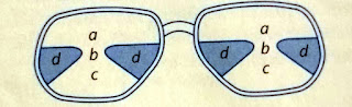
Progressive-add multifocal lenses differ from traditional bifocal or trifocal eyeglasses in that no discrete, visible line divides the distance and reading portions of the lenses (Figure 1.4). Optical compromises required by the manufacturing processes used to eliminate the discrete lines on the lens often produce unwanted cylinder power, distortion, or blurred transistion zones between the distance and near segments, which poses difficulties in performing lensometry. When looking at progressive-add eyeglasses through the lensmeter, take care to select the area with the least distortion in both the distance and the reading portions of the lenses before taking a reading. Be sure to read the add as close to the bottom of the lens as possible. Once the proper areas are found, the lensometry technique is the same as for conventional multifocals. More specific information about the characteristics and uses of progressive-add multifocal lenses appears.

Fig.1.4 Progressive-add bifocals. A transition zone (b) lies between the distance (a) and the near (c) portions. That zone, as well as other areas of the lens (d), contain optical compromises that may make lensometry readings difficult to obtain
LENSOMETRY TECHNIQUE FOR PRISMS:
Lensometry measures not only the power of a prism but also the orientation of the prism's base. The prism orientation may be base in (toward the nose), base out (toward the temple), base up, or base down. Steps for obtaining these measurements are described in the box "Measuring Prism power and Orientation"
MEASURING PRISM POWER AND ORIENTATION:
In general, the existence of prescribed prism power in an eyeglass lens is revealed when the lensmeter mires cannot be centered in the central portion of the lensmeter target. Once you have determined the presence of prism, measure prism power and determine orientation as follows:
1. Count the number of black concentric circles from the central cross of the lensmeter target to the center of the vertical and/or horizontal crossed mires (see figure). Each circle represents 1 prism diopter.

2. Record the direction of the thick portion (base) of the prism by determining the direction of the displacement of the mires. For example, if the mires are displaced upward, the prism base is base up; downward displacement indicates base down; displacement toward the nose, base in; and displacement toward the temple, base out.
Prism compensating devices are incorporated into some lensometers. Such devices permit the measurement of prism without using the concentric circles. To avoid recording prism power that is not actually present when using these devices, be sure that the prism-compensating device is set to zero. Auxiliary prisms are available for use with some lensmeters to assist in measuring glasses with prism power greater than the number of concentric circles.
PLACEMENT OF OPTICAL CENTERS:
For ideal visual correction, the optical center of eye-glass lenses must be placed directly in front of the patient's pupils. The lensmeter may be used to verify the position of the optical center of a lens. Details about the purpose of measuring optical centers of lenses and the Lensometry technique for doing.
Comments
Post a Comment